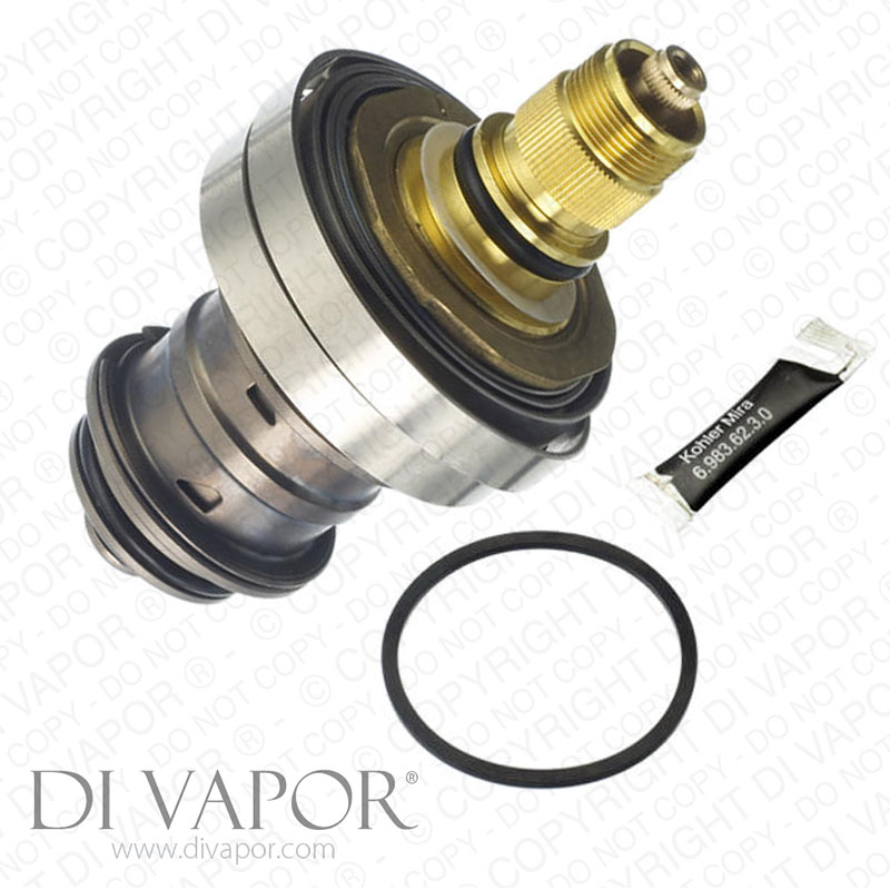
Mira 722 - 902.21 Thermostatic Cartridge Assembly for 722 | G72 | 72 and M72 Low Pressure Shower Mixer Valves


Send a photo of your item and we'll help confirm it.
Summary
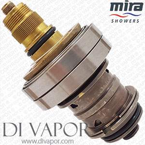
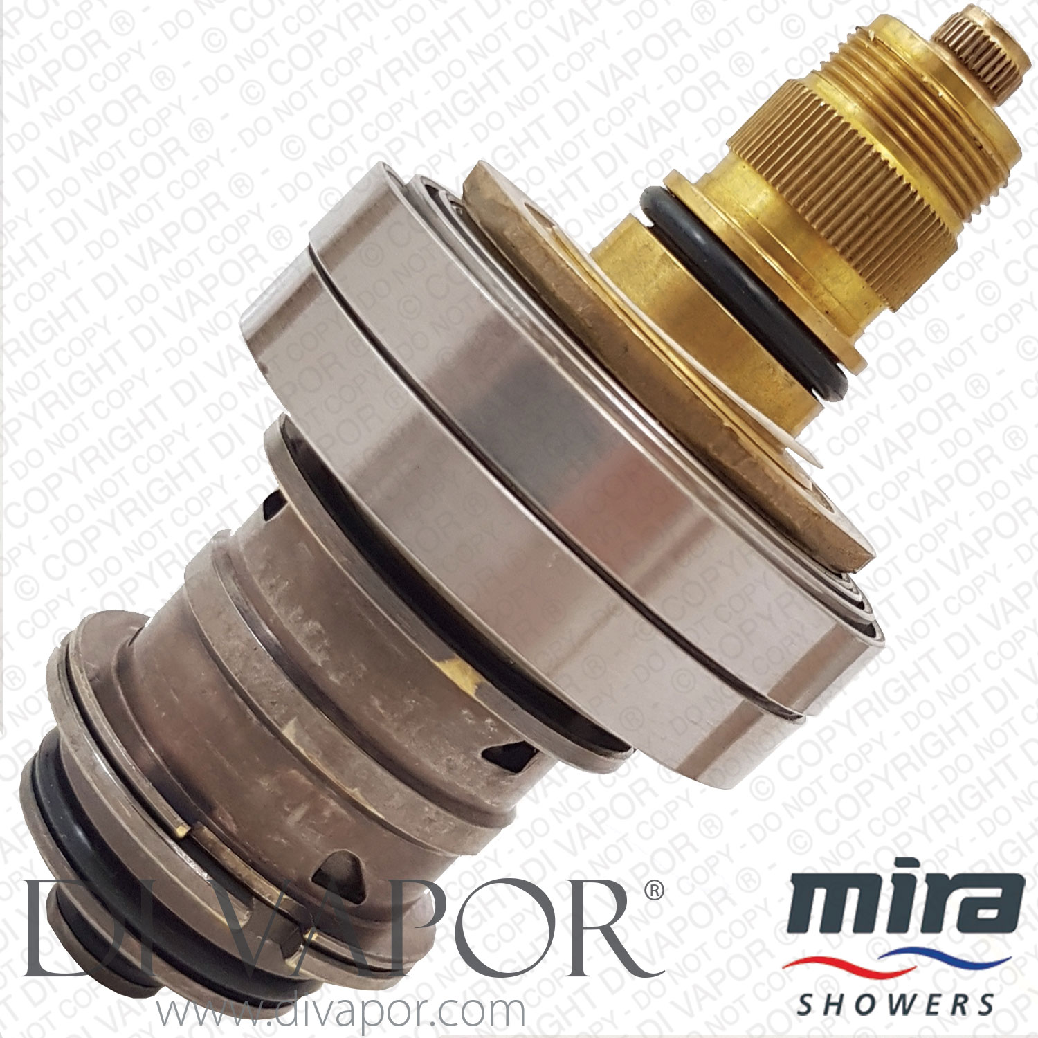
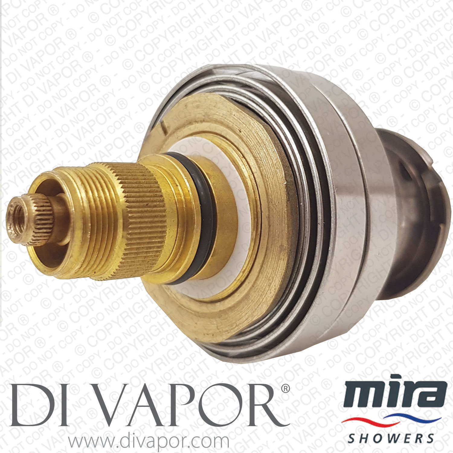
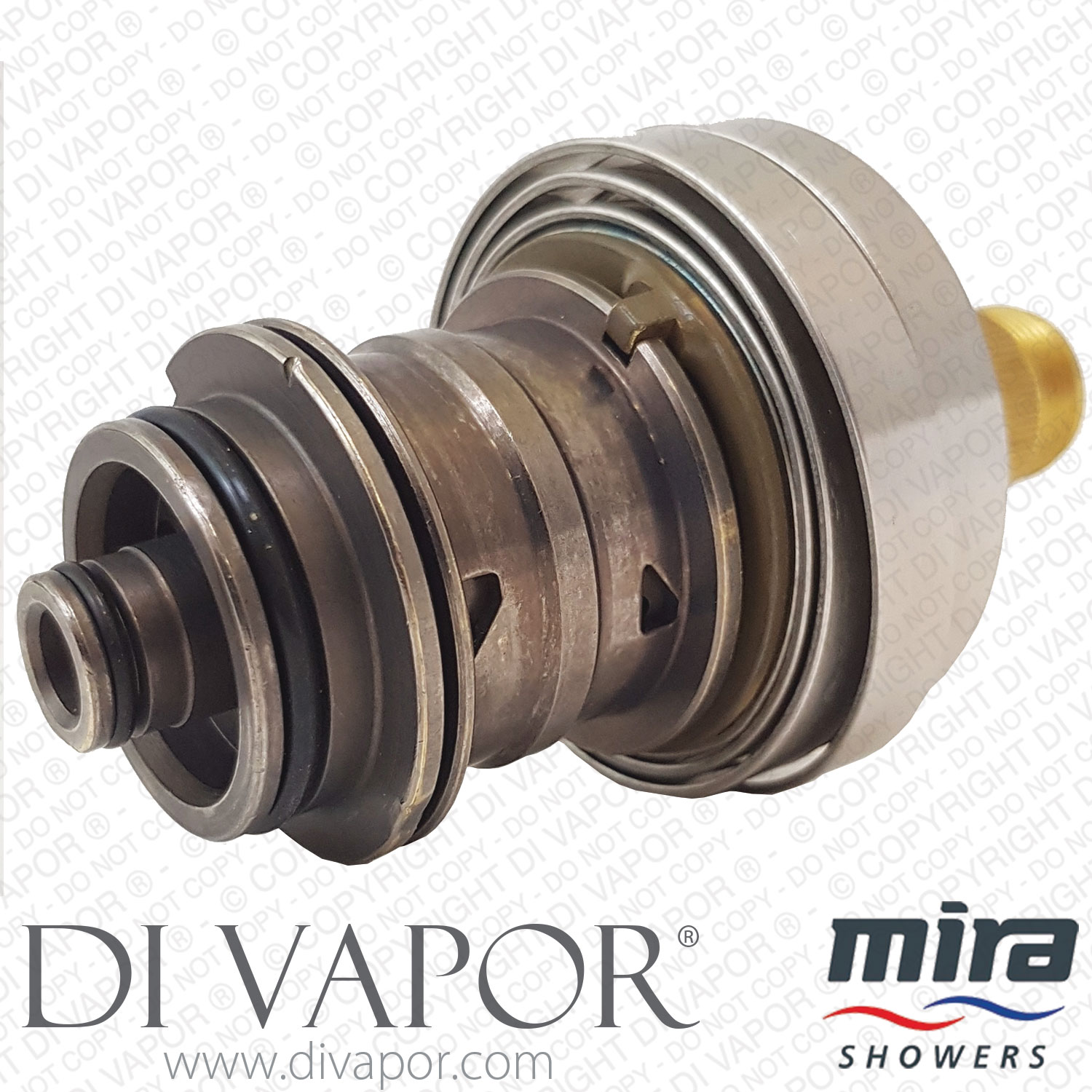
Genuine Rada Mira 722 902.21 thermostatic cartridge assembly for 722 | G72 | 72 and M72 low pressure shower mixer valves.
Included:
- 902.21 thermostatic cartridge
- Large black rubber gasket seal
This cartridge is suitable only for:
- Mira 722 thermostatic mixing valve with standard inlet supplies.
- Mira G72 thermostatic mixing Valve with standard inlet supplies.
- Mira 72 thermostatic mixing valve with reversed inlet supplies.
- Mira M72 thermostatic mixing valve with reversed inlet supplies.
- Rada 722 thermostatic mixing valve with standard inlet supplies.
- Rada G72 thermostatic mixing Valve with standard inlet supplies.
- Rada 72 thermostatic mixing valve with reversed inlet supplies.
- Rada M72 thermostatic mixing valve with reversed inlet supplies.
- Leonard 722 thermostatic mixing valve with standard inlet supplies.
- Leonard G72 thermostatic mixing Valve with standard inlet supplies.
- Leonard 72 thermostatic mixing valve with reversed inlet supplies.
- Leonard M72 thermostatic mixing valve with reversed inlet supplies.
It is not suitable for:
- Rada / Leonard / Mira 722 thermostatic mixing valve with reversed inlet supplies.
- Rada / Leonard / Mira G72 thermostatic mixing valve with reversed inlet supplies.
- Rada / Leonard / Mira 72 thermostatic mixing valve with standard inlet supplies.
- Rada / Leonard / Mira M72 thermostatic mixing valve with standard inlet supplies.
Mira 722 / 902.21 Cartridge Technical Specifications:
| Total Length | 112mm |
|---|---|
| Width at widest point | 57mm (just above thread) |
| Material | Brass |
| Installation Type | Push fit |
| Number of O-Rings | (8 altogether with part numbers as follows) |
- Mira 630.04
- Mira 630.08
- Mira 630.21 (2 of them)
- Mira 630.23
- Mira 630.36
- Mira 630.41
- Mira 630.66
Gasket / shim / washer part numbers:
- Mira 634.08
- Mira 636.17
- Mira 636.25
Instructions for fitting a replacement cartridge assembly to a Mira, Rada or Leonard thermostatic 72, 072 or 722 mixing valve
The fitting of a replacement cartridge assembly is a simple operation providing the following instructions are carefully followed stage by stage. If, after reading the instructions, you are in doubt about the procedure, you must seek the assistance of a qualified person locally. First turn off the hot and cold water supplies. Open the flow control to release built-up pressure. The appropriate section in this leaflet e.g. Mira thermostatic 72, G72 or 722, whichever is applicable, must now be followed.
Mira thermostatic 72 Dismantling
If your mixing valve is a built- in model, remove the two adjusting screws and angle the concealing plate away from the mixing valve. Remove the flow control knob retaining bolt and pull off the flow control knob. Unscrew the spring retainer and remove the friction spring. Pull the temperature regulating lever off its spline and lift off the thrust washer. Remove the four cover screws.
Lift the cover away from the body (when doing this a small amount of residual water will run from the mixing valve, so if you have a built-in model You may prefer to channel it away, or to use absorbent material to soak it up). Pull off the thermostat assembly or push it out if it has been retained by the cover. Pull the port assembly from the body. If necessary, refit the flow control knob and retaining bolt to use as extra grip. Remove the cover joint.
Re-assembly
Fit the new cover joint supplied with the cartridge assembly. Fit the port assembly into the body, locating the cutaway at the bottom of the pillar and the sleeve over the lug in the body and push into position. A smear of silicone based lubricant `on the exposed lower seals, also the head nut seal, of the port assembly, will assist in fitting of this part. Similarly smear the exposed seal above the coils of the thermostat assembly. The port sleeve will then be free to rotate within the limits of its travel. Fit the thermostat assembly over the spindle, engaging its projection in the slot of the port sleeve.
Recheck that the port sleeve is positioned so that its cutaway is over the lug and that the flange is not trapped on top of the lug. Failure to check this could cause damage when the cover is re- placed. Replace the cover, refit and tighten the four cover screws. Turn on the water supplies, carefully at first, making sure that there are no leaks, then turn on the mixing valve to full flow.
Gripping its spline by hand, rotate the thermostat assembly until the required maximum temperature is obtained (clock- wise to increase the temperature and anticlockwise to de- crease it). Replace the thrust washer. Replace the temperature regulating lever on the spline, so that its position lines up with the number 5 on the scale. If it is correctly positioned the stop screw in the cover will prevent further rotation in a clockwise direction. Replace the friction spring and screw down the spring retainer.
Fit the flow control knob and replace the flow control knob retaining bolt. Open the flow control and recheck the maximum temperature set- ting. If it is not to your satisfaction repeat the procedure until satisfaction is obtained.
If your mixing valve is a built-in model, angle the concealing plate over the temperature regulating lever until it is in position and refit the adjusting screws.
Mira thermostatic 072 and 722 If your mixing valve is a built- in model
Mira thermostatic G72. Remove the two adjusting screws and angle the concealing plate away from the mixing valve.
Mira thermostatic 722. Prise off the concealing plate (prise off in centre.- not at ends). Remove the bracket screws and lift away the concealing plate mounting bracket.
Dismantling
Remove the flow control knob retaining bolt. Pull off the flow control knob. Unscrew the two attachment screws and remove the temperature regulating assembly from the cover as a complete unit. Remove the four cover screws. Lift the cover away from the body (when doing this a small amount of residual water will run from the mixing valve, so if you have a built-in model you may prefer to channel it away or to use absorbent material to soak it up).
Pull off the thermostat assembly or push out if it has been retained by the cover. Pull the port assembly from the body. If necessary refit the flowcontrol knob and retaining bolt to use as extra grip. Remove the cover joint.
Re-assembly
Fit the new cover joint supplied with the cartridge assembly. Fit the port assembly into the body, locating the cutaway at the bottom of the pillar and the sleeve over the lug in the body and push into position. A smear of silicone based lubricant on the exposed lower seals, also the head nut seal, of the port assembly, will assist in fitting of this part. Similarly smear the exposed seal above the coils of the thermostat assembly. The port sleeve will then be free to rotate within the limits of its travel.
If you are servicing a Mira thermostatic G72E or 722E model, replace the spring Over the spindle before fitting the thermostat assembly. Fit the thermostat assembly over the spindle, engaging its projection in the slot of the port .sleeve. Recheck that the port sleeve is positioned so that its cutaway is over the lug and that the flange is not trapped on top of the lug.
Failure to check this could cause damage when the cover is replaced Replace the cover. Refit and tighten the four cover screws. Turn on the water supplies carefully at first, making sure that there are no leaks, then turn on the mixing valve to full flow.
Gripping its spline by -hand rotate the thermostat assembly until the required maximum temperature is obtained (clock- wise to increase the temperature and anticlockwise to de- crease it). Move the temperature regulating lever to the limit of its travel so that the indicator is at position 5 On the scale. With the indicator in this position, replace the temperature regulating assembly on the spline of the thermostat assembly, making sure that the two holes in the assembly are lined up with the two threaded holes in the cover. Push the temperature regulating assembly down onto the spline of the thermostat assembly.
Replace the two attachment screws. Do not over tighten. Replace the flow control knob and nameplate. Tighten the flow control knob retaining bolt. Open the flow control knob and recheck the maximum temperature setting. If it is not to your satisfaction it is possible that you inadvertently rotated the thermostat spline when fitting the attachment screws, so that they will have to be re- moved and the procedure repeated until satisfaction is obtained. If your mixing valve is a Mira thermostatic G72 built-in model, angle the concealing plate over the temperature regulating lever until it is in position and refit the adjusting screws.
If your mixing valve is a Mira thermostatic 722 built-in model, having refitted the concealing plate mounting bracket, angle the concealing plate over the temperature regulating lever and locate it in position on the concealing plate mounting bracket. Then press so that it snaps into position.
Fast delivery
- UK delivery: £5.95 incl. VAT for this small packet item.
- For all in-stock spare parts the typical UK delivery timescale is 2-5 working days.
- If you need a part urgently then we can provide a next-day (delivered Mon-Fri) UK delivery service for all in-stock small parcels ordered before 3.00pm, Monday - Friday.
- Next day delivery is available to select at an additional charge during the checkout.
- Worldwide delivery available — see our delivery page for details.
Returns
- 14 days 'risk-free' returns.
- Start a return within 14 days of receiving your order by calling 0121 705 0866 or using our contact page.
- Full returns information is available in our terms and conditions.
Payment methods
We accept the following payment methods:

- Card payments: Visa, Mastercard, Maestro, Discover, JCB, Diners Club and EnRoute
- PayPal
- American Express: available via PayPal guest checkout only
- BACS bank transfer
- Cheque: dispatch takes place once payment has cleared
Security
We use industry-standard payment systems to help keep your payment information secure. Our website and payment processes are regularly checked to maintain PCI security standards.
- Secure SSL encryption
- Your personal and payment details are protected
- Regularly checked for PCI security standards